LLDP Tool
This post is a follow-up to the creation of my MAC address reader tool.
In this post, I find a new use case for the tool, and document a new and improved prototype of the hardware.
Problem Statement
Switch Ports
The MAC address reader tool uses an Arduino platform to extract the MAC address of the connected device from an Ethernet packet header. It is a helpful tool for data collection when stuck without a portable computer, as it is wired up to accept 5v power, which is easily supplied by any USB portable charger.
During the months after creating the MAC Address reader, I encountered a related inefficiency while working at some large client sites. Namely, determining the identity of unlabelled network points, in order to diagnose connection issues, and assist the (often remote) client IT personnel with network changes.
The main time sinks were:
- Determining the physical switch and switch port that an Ethernet wall point was connected to, for patching purposes; and
- Determining the current VLAN number once patching was complete as specified.
Protocols
I experienced a flashback to CCNA training manuals of the distant past, and
recalled that there is a protocol called CDP, or
Cisco Discovery Protocol,
which advertises this information and more over the network from their
routers and switches. However, the clients I was engaging with at the time were
not using Cisco hardware.
A small amount of searching brought up the Link Layer Discovery Protocol, which is an open standard to accomplish the same goal, with wide adoption. I decided, after reading the protocol specification, that this information should be able to be parsed and displayed on my MAC Address Reader.
There are a lot of data fields in the LLDP specification, each of which may or
may not be included for any given type of equipment. For my use case, I am
interested in the connected device name, the text representation of the port
number, the VLAN number(s) applicable to the port, and the operational modes
of the port (e.g. routing enabled). This is because I am mainly connecting to
network switches.
The Code Rewrite
After a rewrite, and some trial and error to fit the relevant
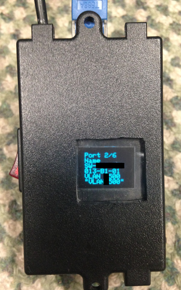
information on the 64x48px display, I was able to create a program
incorprating LLDP parsing functionality for the MAC address reader hardware.

The sad fact is, however, that the small MicroView display was overextended. A new prototype was called for, and this time I wanted to make use of a 3D printer which I had recently acquired.
New Prototype
Parts & Enclosure
I acquired the following parts in preparation, and took measurements.
- 1x ENC28J60 Ethernet 5v module (pinout may vary!)
- 1x 0.96" SSD1306 SPI OLED module
- 1x Arduino Pro Mini 5V board
- 1x Rocker Switch
- 1x deconstructed portable USB battery bank charge management PCB
- 1x 18650 battery cell
Note that the links provided above are for reference only. A cheaper supplier was used to provide the Ethernet and OLED modules; I would recommend shopping around.
As I am more familiar with code than with CAD, I thought that a programmatic method of modelling the enclosure might be worth a look, and thus after some research I stumbled upon an open source parametric CAD program called openscad.
This allows precise measurements to be used as variables for all needed cutouts, and objects such as the small PCB mounting pins to be specified once as a function, and re-used all over the design with any desired scaling, rotation, etc.
It's not perfect for artistic work, and is likely far more difficult to use for one-off projects than a good direct modeling CAD tool, but I liked the concept and wanted to try it out.
Some days later, I had completed a 3D model of the enclosure, and was ready to print! I have included a WebGL preview of the model below. Feel free to activate it with the link, and rotate it around.
I could have used more variables and fewer magic constants in the model code. However, the model worked, and the code was extensible enough to copy and move around all of the parts that needed to be moved.
Putting It Together
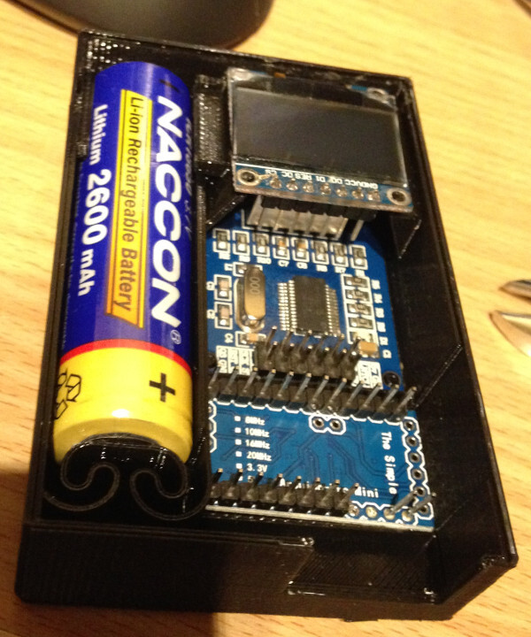
After printing the enclosure in around 11 hours, I discovered that some of my tolerances were wrong, particularly around the segment intended to house the battery charging micro-usb port. The battery itself was too tall when placed into the holder. The charging board did not fit above it.
As this is not critical for a prototype, I continued regardless. Test fitting the primary parts worked very well, as shown in the below image.

Notably, a piece of plastic above the on / off toggle switch has been manually cut out. This is because the switch fits better when slid in from above.
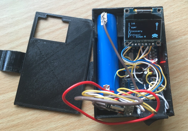
After connecting both the OLED and the Ethernet modules to the Arduino's SPI bus with some wires and solder, and connecting the 5v output from the battery charge management board into power for everything, I had successfully created a functional new prototype!

UPDATE: I have drawn a schematic of the necessary connections, excluding the power circuitry. Hopefully this is useful.
The battery charge management board floats inside the prototype, and recharging the device requires opening the enclosure. This will require a fix, eventually.
Writing The Code
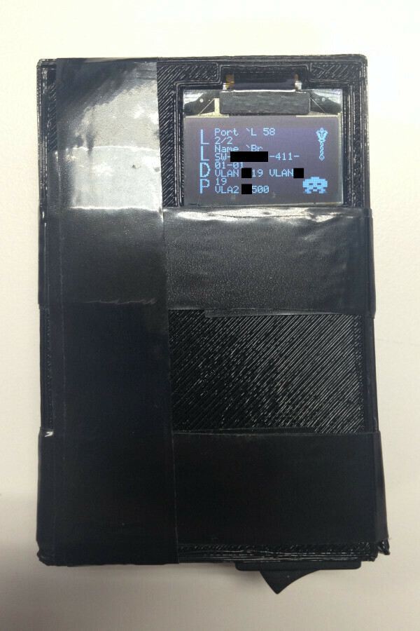
With a 128x64 pixel display on this OLED, I had far more space to include
text from the LLDP packets, and I was able to add some imagery as well! I drew
a pixellated mace for decoration, and included the Space Invader from the
Microview standard icon library.
The main items of interest to me remained the VLAN numbers and names. With more space for switch names, I could comfortably include any secondary VLANs without any concerns about running out of screen space.
In order to draw a custom font while still saving flash memory for unnecessary graphics, I included only actively used letters in the generated font structure, and included data for graphics in the unused space where other letters were originally stored.
You can read the code for this prototype in my Arduino repository.
It is possible to determine the correct wiring by reading the code and some documentation. If you are looking to duplicate my work, I would suggest designing a PCB instead of using wires. The process of putting this prototype together with wires would be frustrating regardless of how skilled you may be at soldering; the time is better spent designing a better way to do it!
End Result
The lid was... shall we say, not tight enough to seal the device closed. The nozzle width of the 3D printer was not narrow enough to print at the desired level of detail, and my temperature control was not yet tuned correctly for the PLA filament used. Since the lid had no chance of staying on by itself, my go-to solution was electrical tape. It is a prototype, after all.
For the next prototype, I will likely investigate creating a custom PCB with the ATMega328 and ENC28J60 microcontrollers directly connected together, and the OLED as well if possible!
This prototype device is already very useful on client sites, and is a timesaver compared to carrying around a laptop and running wireshark, especially when comparing switch connection information for multiple Ethernet wall points.
